Installing a UTV winch correctly matters as much as choosing the right capacity. Poor mounting, weak grounding, or improper rope setup can reduce pulling power, overheat components, and cause failures under load.
Winch performance depends not only on rated pull but on how capacity, vehicle weight, electrical limits, and recovery setup interact under real load conditions—factors that are often misunderstood when choosing a winch.
This guide walks through proper UTV winch installation—from mounting and wiring to rope spooling and first-pull testing—using practical setup details that prevent the most common real-world problems. It applies to most 3,500–4,500 lb UTV winches and focuses on reliability, electrical safety, and consistent performance in recovery situations.
Jump To Contents
- UTV Winch Installation Basics: Mounting, Wiring, and First-Time Setup
- Tools and Parts Needed to Install a UTV Winch
- Step-by-Step UTV Winch Installation Process
- Step 1: Mounting the Winch to the UTV Frame or Mounting Plate
- Step 2: Installing the Fairlead Correctly
- Step 3: Wiring the Winch to the Battery Safely
- Step 4: Connecting the Solenoid and Winch Controls
- Step 5: Spooling the Winch Rope and Performing the First Pull Test
- How Many Wraps Should Stay on a UTV Winch Drum?
- UTV Winch Installation Checklist – Quick Reference
- Common UTV Winch Wiring Mistakes to Avoid
- Should You Install a UTV Winch Yourself or Have a Shop Install It?
- How Proper Installation Affects Winch Performance and Safety
- Installation Quality Directly Affects Pulling Performance
- Electrical Installation Determines Dependability Under Load
- Correct Setup Improves Recovery Safety
- Installation Completes the Recovery System
- UTV Winch Installation FAQs
- How long does it take to install a UTV winch?
- Do I need a fuse or circuit breaker for a UTV winch?
- Should a UTV winch be grounded to the frame or battery?
- How many wraps should stay on the winch drum?
- Why does my winch work without load but slow down under load?
- Can I install a winch on a stock UTV battery?
- Final Takeaway: Proper Installation Determines Winch Reliability
UTV Winch Installation Basics: Mounting, Wiring, and First-Time Setup
Installing a UTV winch isn’t just about bolting it on and hooking up power. On common setups—like a 4,500-lb winch mounted to a Polaris Ranger or Can-Am Defender—the details of mounting alignment, wiring, and rope setup determine whether the winch pulls smoothly or struggles under load.
At a high level, installation follows this sequence:
1. Mount the Winch Securely and square.
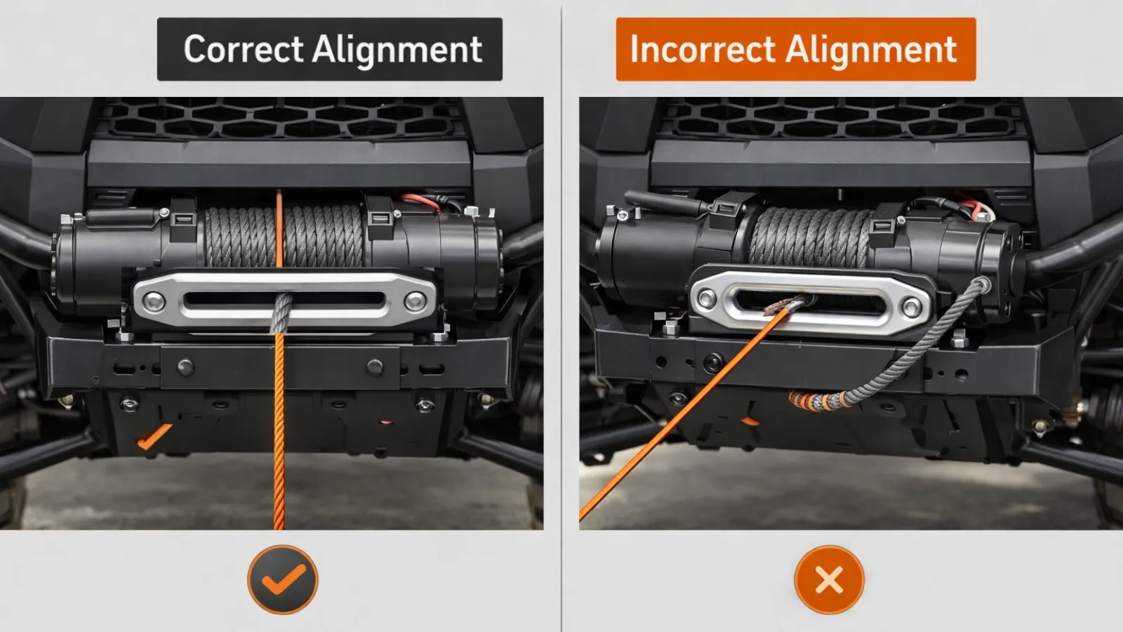
The winch must sit straight on a dedicated mounting plate so the rope feeds evenly across the drum. Be careful of misalignment, as it causes rope stacking, side loading, and increased motor strain.
2. Install the Correct Fairlead
Fairleads protect the rope at the exit point:
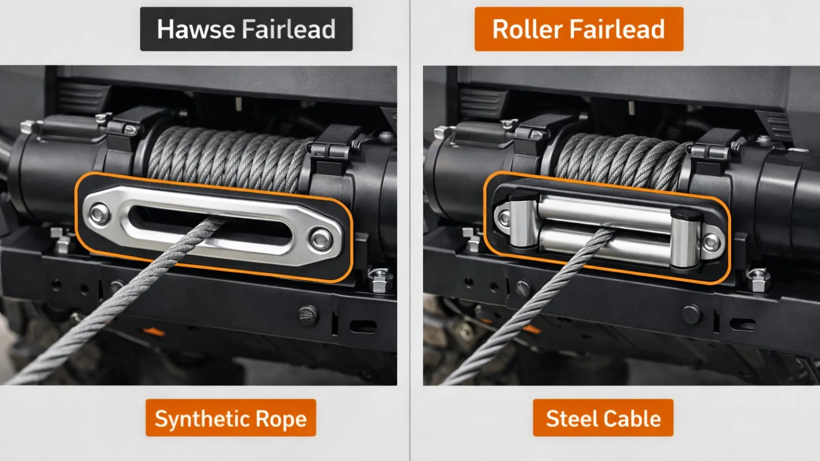
- Synthetic rope → Hawse fairlead
- Steel cable → Roller fairlead
Fairlead choice is directly tied to rope material decisions, which affect abrasion resistance, heat buildup, and recovery safety when comparing synthetic rope vs steel cable for UTV winches.
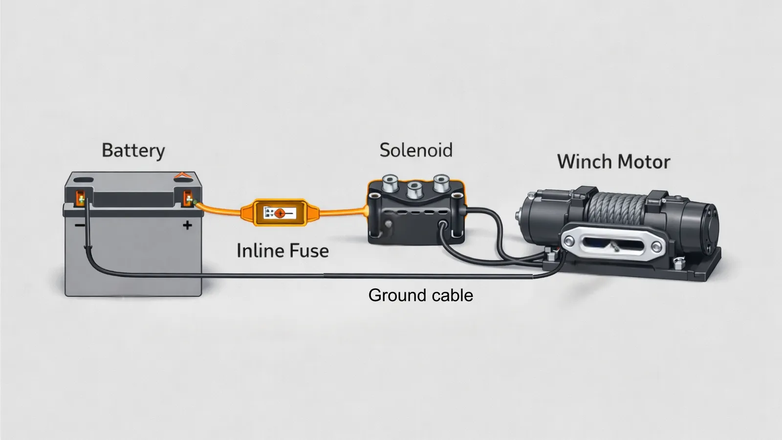
3. Wire the Winch Directly to the Battery
Use an inline fuse or circuit breaker in the positive lead to protect the electrical system. This step is mandatory to prevent overloads or electrical shorts. Ensure the ground connection is solid, as poor grounding is the most common cause of slow winch speed and overheating.
4. Spool the Rope and Perform a First-Pull Test
Initial spooling under light tension prevents rope burying. A controlled test pull confirms solenoid operation, correct polarity, and control response before trial use.
When done correctly, installation ensures the winch operates within the UTV’s electrical limits and delivers controlled pulling power when traction is lost.
When a winch doesn’t perform the way people expect, it’s rarely because the winch itself is defective. In most cases, something was overlooked during installation—usually wiring, grounding, or alignment—and the problem only shows up once the winch is under load.
Tools and Parts Needed to Install a UTV Winch
UTV winch installation tools and components include mounting hardware, electrical protection, and control interfaces required to securely integrate the winch with the UTV’s frame and battery system.
Preparing all tools and parts before installation prevents rushed wiring, improper mounting, and unsafe electrical shortcuts. Organize your tools and equipment in advance to save 10-15 minutes during installation and significantly reduce wiring errors.
Essential Winch Components
UTV Winch
Electric winch sized appropriately for the machine – typically 3,500 or 4,500 lb. The drum should free-spool easily before mounting.
Winch Mounting Plate or Model-Specific Bracket
A dedicated plate ensures proper alignment with the fairlead and distributes the load through the frame rather than relying on plastic bumpers or improvised brackets.
Fairlead (Matched to Rope Type)
- Hawse fairlead → synthetic rope
- Roller fairlead → steel cable
Winch Solenoid / Contactor
Regulates power flow to the motor. Must be mounted away from direct water spray and engine heat.
Control Interface
Wired remote, handlebar switch, or wireless controller (if included). Controls should be tested before final mounting.
Electrical and Safety Components
Inline Fuse or Circuit Breaker (Required)
Protects the UTV’s electrical system from overloads and short circuits. Installed as close to the battery’s positive terminal as possible.
Heavy-Gauge Winch Wiring Harness
Supplied with most winches. Cables must reach the battery without tension and avoid heat or moving parts.
Battery Terminal Hardware
Clean, corrosion-free connections are critical for high-current draw under load.
Basic Tools Required
- Socket set and ratchet
- Wrenches (metric or SAE, depending on hardware)
- Torque wrench (recommended)
- Zip ties or split loom for cable management
- Safety gloves and eye protection
Optional but Recommended
- Dielectric grease for electrical terminals
- Heat shielding near exhaust routing
- Multimeter for voltage and continuity checks
Items like tree savers, rated shackles, and snatch blocks are often treated as add-ons, but they directly affect recovery safety and load management, making them part of essential UTV winch accessories rather than optional add-ons.
Once tools and components are prepared, proceed with installation. Begin by mounting the winch to ensure it pulls straight and evenly, without frame flex.
Step-by-Step UTV Winch Installation Process
Step-by-step UTV winch installation is a sequential process in which mounting alignment, fairlead selection, and electrical wiring must be completed to ensure consistent pulling power, electrical safety, and durability.
Each step below is based on the previous one. Skipping or reordering steps commonly leads to rope binding, voltage drop, or intermittent winch operation under load.
Step 1: Mounting the Winch to the UTV Frame or Mounting Plate
Winch mounting is the mechanical process of securing the winch squarely to the UTV frame so pulling forces are transferred evenly and the rope feeds straight onto the drum.
Correct mounting directly affects rope tracking, motor load, and frame stress during recovery.
Position the Winch on a Dedicated Mount
- Use a UTV-specific winch mounting plate or bumper mount.
- The mount should be designed to distribute the load into the frame, not plastics or thin brackets.
- Improvised mounts often flex under load, leading to misalignment.
Align the Winch Drum With the Fairlead Opening
The rope must exit the drum in a straight line. To check alignment, place a straightedge across the drum and extend it through the fairlead. This visual check helps identify misalignment early. Even minor offsets cause rope stacking and side-loading, increasing heat buildup and rope wear.
Secure All Mounting Hardware Evenly
- Install all supplied bolts—do not omit hardware.
- Tighten bolts evenly and torque to manufacturer specifications.
- Uneven torque allows the winch to move under load.
A winch can look perfectly fine once it’s bolted in, but even slight misalignment shows up later as uneven rope stacking or extra strain on the motor. We’ve seen mounts that held solid but still caused problems simply because the drum wasn’t feeding straight through the fairlead.
Step 2: Installing the Fairlead Correctly
Fairlead installation ensures the winch rope is guided onto the drum with minimal friction and abrasion during straight and angled pulls.
Fairlead type must always match rope type—this is a functional requirement, not a preference.
Match Fairlead to Rope Type
Synthetic rope → Hawse fairlead
- Smooth, radiused surfaces prevent fiber cutting and heat damage.
Steel cable → Roller fairlead
- Rollers reduce friction and prevent cable flattening or kinking.
Using the wrong fairlead accelerates rope degradation and increases the risk of failure under load.
Center the Fairlead With the Winch Drum
- The rope should pass through the fairlead without contacting the edges.
- Misalignment increases abrasion regardless of rope material.
- Inspect alignment before fully tightening fairlead bolts.
Step 3: Wiring the Winch to the Battery Safely
UTV winch wiring is the process of delivering high-current power from the battery to the winch motor with minimal resistance while protecting the electrical system from overload or short circuits.
If a winch runs slowly, inconsistently, or overheats, the motor usually isn’t the problem. Wiring issues—especially poor grounds or high resistance—are far more common and often don’t show up until the winch is actually pulling. For example, a voltage drop of more than 0.5 V under load may indicate a grounding problem. Applying specific measurements helps turn general warnings into actionable diagnostic tests.
Recommended Winch Wire Gauge by UTV Winch Capacity
Before routing or modifying any wiring, it helps to confirm that the cable size matches the winch’s current draw. Undersized wiring is one of the most common causes of slow line speed, excessive heat buildup, and premature solenoid failure.
| Winch Rated Capacity | Typical Current Draw (Under Load) | Recommended Cable Gauge |
| 2,500 – 3,000 lb | 150 – 200 A | 6 AWG |
| 3,500 lb | 200 – 275 A | 4 AWG |
| 4,000 – 4,500 lb | 250 – 350 A | 2 AWG |
| 5,000 lb+ (UTV use) | 300 – 400+ A | 1/0 AWG |
These recommendations assume a short cable run typical of UTV installations. If the wiring path is longer than stock, routed through the cab, or used frequently under heavy load, stepping up to the next cable size helps reduce voltage drop and heat buildup.
Excessive heat during testing is often a sign of electrical resistance or duty-cycle limits rather than a defective motor, especially in smaller electrical systems with limited recovery runtime, which ties directly into UTV winch duty-cycle limits.
Connect the Positive Lead Directly to the Battery
- Route the positive cable from the solenoid to the battery’s positive terminal.
- Use only the supplied heavy-gauge wiring.
- Avoid stretching, splicing, or downsizing cables.
Install an Inline Fuse or Circuit Breaker
- Required for electrical system protection
- Must be installed as close to the battery’s positive terminal as possible
- Protects against wiring faults and overload conditions
Skipping this step risks damage to the battery, stator, solenoid, or wiring harness.
Establish a Solid Ground Connection
- Ground directly to the battery’s negative terminal when possible
- Avoid painted, corroded, or thin frame grounds.
- Poor grounding causes voltage drop, slow line speed, and overheating.
We’ve run into this most often on Polaris Ranger installations where the ground was tied to a painted frame tab. The winch would free-spool normally but slow down dramatically under load. Running the ground cable directly to the battery’s negative terminal solved the issue immediately.
Route Wiring Away From Heat and Movement
Avoid routing cables near exhaust components and engine heat. Before installation, assess whether any cable could come into contact with the exhaust after extended use. Identify potential hazards that could not be immediately obvious. And keep wiring clear of suspension and steering components, and use a loom to secure cables and prevent chafing.
A winch that pulls slowly or inconsistently under load is more likely to be suffering from grounding or resistance issues than from insufficient winch capacity.
Step 4: Connecting the Solenoid and Winch Controls
Winch solenoid and control installation involves routing and mounting the electrical switching system that directs battery power to the winch motor in response to user input.
Correct solenoid placement and control wiring determine response reliability, direction accuracy, and electrical safety.
Mount the Solenoid in a Protected Location
- Choose a location shielded from direct water spray, mud packing, and engine heat.
- Even sealed solenoids deteriorate more quickly when repeatedly submerged.
- Avoid mounting directly above exhaust components or low splash zones.
A poorly placed solenoid often fails long before the winch motor does.
This tends to show up after longer rides. Everything works fine initially, but after heat builds in the engine bay, a poorly placed solenoid starts acting intermittently. We’ve seen this cause delayed response or random cutouts during recovery pulls.
Connect Winch Motor Leads Exactly as Labeled
- Match cables to the solenoid terminals per the manufacturer’s diagram
- Reversed polarity can cause the winch to spool in the wrong direction.
- Misconnections may prevent operation or damage the solenoid.
Labeling cables before routing reduces installation errors.
Install and Position Winch Controls
- Mount wired remotes or handlebar switches where they are reachable but protected.
- Ensure cables do not interfere with steering or suspension movement.
- If a wireless remote is included, pair it before finalizing installation.
Verify Control Response Before Finalizing
- Test IN and OUT functions with no load.
- Confirm immediate stop when controls are released.
- Look for slow response or intermittent activation.
Control response and failure behavior also vary depending on whether the system uses a wired or wireless interface, especially under load or low-voltage conditions, which is why wired vs wireless winch remotes matter during recovery.
Step 5: Spooling the Winch Rope and Performing the First Pull Test
Taking a few extra minutes to spool the rope correctly and run a light test pull makes a big difference later. It helps the rope seat evenly on the drum and confirms that everything—from controls to wiring—is working the way it should.
This step determines the rope’s long-term behavior and recovery reliability.
How to Spool a UTV Winch Rope Correctly
Initial rope spooling sets the foundation for all future pulls. Improper spooling leads to rope burying, binding, and reduced pulling efficiency.
Start in Free-Spool Mode
- Disengage the clutch and pull the rope out by hand.
- Feed the rope straight through the fairlead.
- Inspect for twists, kinks, or shipping damage before tensioning.
Apply Light, Even Tension During Spooling
- Re-engage the clutch and slowly power the rope in.
- Apply light resistance by hand or using a fixed anchor on flat ground.
- Keep steady tension to form tight, even wraps on the drum.
How Many Wraps Should Stay on a UTV Winch Drum?
Winch pulling power depends on the rope layers closest to the drum. Removing too much rope reduces braking grip and increases the risk of the rope slipping under load.
Use the guidelines below during spooling and setup.
| Rope Type | Minimum Wraps on Drum | Practical Recommendation |
| Synthetic Rope | 5 wraps | 6–8 wraps for safety |
| Steel Cable | 4 wraps | 5–6 wraps recommended |
Keeping these wraps on the drum ensures the rope anchor point is never loaded directly. The winch develops its rated pulling power only when the inner wraps remain tight and secure.
Important: Never pull until only one or two wraps remain on the drum. This significantly reduces holding strength and can cause the rope to slip or detach under load.
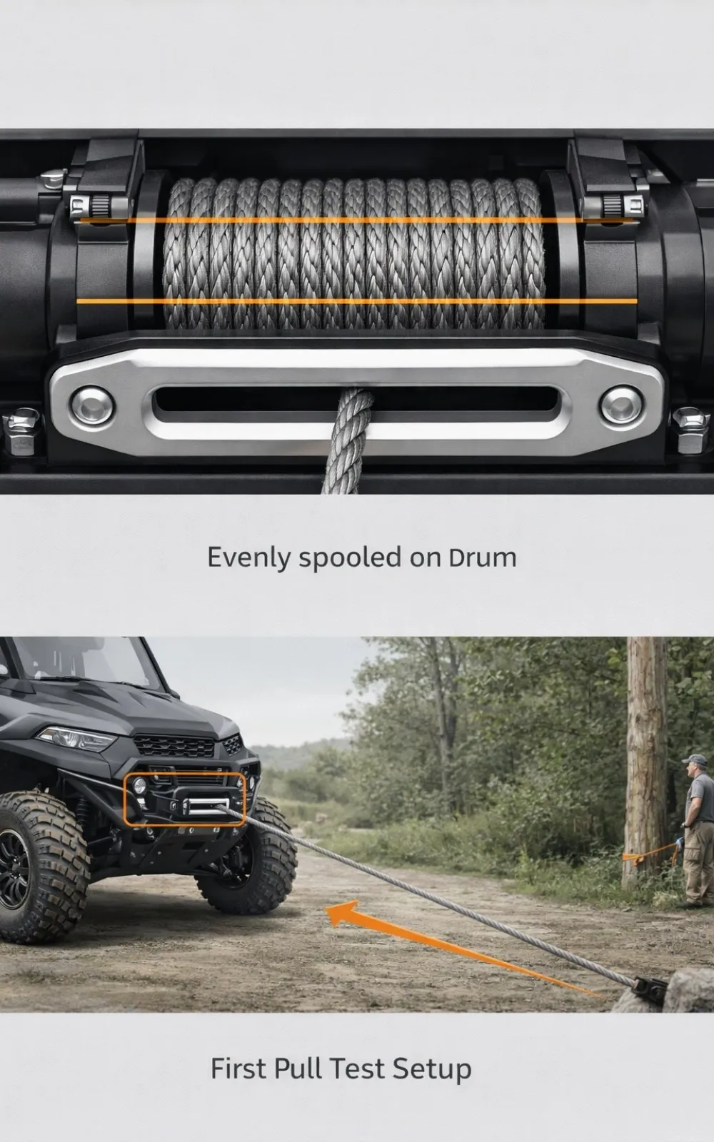
Keep Rope Aligned Across the Drum
- The rope should stack side to side.
- Stop immediately if stacking occurs on one side
- Correct alignment before continuing
Do not rush this process—slow spooling prevents long-term issues.
Taking a few extra minutes to spool the rope under light tension pays off later. I’ve found that most rope-burying issues trace back to rushed first spooling, especially when the first real pull happens on uneven ground.
This step determines the long-term behavior and recovery reliability of the rope. Combine sensory indicators with technical checks during this phase. If you notice unexpected smells, such as hot electrical insulation, stop immediately and reassess the installation to prevent potential hazards.
First-pull testing confirms correct wiring, solenoid function, rope behavior, and control reliability before real recovery use.
Perform a No-Load Function Test
- Power the winch IN and OUT with no resistance. Confirm smooth, immediate response. Listen for abnormal noises such as grinding or clicking. Address any hesitation before applying the load.
- Anchor to a solid object (tree, anchor point)
- Keep the pull straight and short.
- Apply minimal load to seat the rope and confirm pulling power.
Avoid angled or heavy pulls during this stage.
Monitor Electrical and Thermal Behavior
- Watch for slow line speed or flickering lights.
- Feel the motor and solenoid housing for excessive heat
- Stop immediately if heat builds rapidly
Heat buildup at low load usually indicates wiring resistance or grounding issues.
Test Control Reliability
- Verify wired remote operation
- If wireless, test from multiple positions
- Confirm instant stop when controls are released
Reliable control response is a safety requirement, not a convenience feature. Proper spooling and initial testing complete the installation process by validating that the winch selection, electrical capacity, and setup work as a system—not as isolated components.
Many recovery injuries occur during initial pulls due to improper setup or control mistakes, reinforcing the importance of proper UTV winching safety practices during testing and real-world recovery.
UTV Winch Installation Checklist – Quick Reference
Use this checklist to verify a UTV winch installation before trail or work use. Most winch problems occur when one of these steps is skipped.
Mounting & Alignment
- ☐ Winch mounted square to frame or mounting plate
- ☐ All mounting bolts installed and torqued evenly
- ☐ Winch drum aligned straight with fairlead opening
Fairlead & Rope
- ☐ Fairlead matches rope type (hawse for synthetic, roller for steel)
- ☐ Fairlead centered; rope does not contact edges
- ☐ Minimum wraps on drum: synthetic (5+), steel (4+)
Wiring & Electrical
- ☐ Positive cable runs directly to battery with no splices
- ☐ Inline fuse or circuit breaker installed near battery positive
- ☐ Ground cable connected directly to battery negative
- ☐ Wiring secured away from heat, exhaust, and moving parts
Solenoid & Controls
- ☐ Solenoid mounted away from heat and splash zones
- ☐ Motor leads connected as labeled
- ☐ IN and OUT directions verified
- ☐ Controls stop immediately when released
Initial Test
- ☐ No-load IN/OUT test completed
- ☐ Light straight pull performed on flat ground
- ☐ Rope spooled evenly across drum
- ☐ No excessive heat at motor or solenoid
If all items are checked, the winch installation is ready for normal recovery use.
Common UTV Winch Wiring Mistakes to Avoid
As noted earlier, most winch problems stem from wiring issues, especially grounding and circuit protection. Most trail-side winch problems stem from one or more of the issues below.
Skipping the Inline Fuse or Circuit Breaker
Inline circuit protection prevents electrical damage if a short or overload occurs during winch operation.
- Protects the battery, solenoid, and stator from current spikes
- Must be installed close to the battery’s positive terminal
- Often included in winch kits but incorrectly omitted during installation
Without protection, a wiring fault can damage the UTV’s electrical system before the winch itself fails.
Poor or Incomplete Ground Connections
Improper grounding increases electrical resistance, resulting in a voltage drop under load.
- Grounding to painted or corroded frame points increases resistance.
- Weak grounds cause slow line speed, overheating, and solenoid stress.
- Direct battery-negative grounding provides the most reliable return path.
A winch that works intermittently or only under light load is almost always suffering from a grounding issue.
Using Undersized, Extended, or Modified Wiring
Incorrect cable sizing restricts current flow on high-draw systems like UTV winches.
- Never downsize cable gauge to simplify routing.
- Avoid splicing winch cables unless absolutely necessary.
- Longer cable runs increase resistance and heat buildup.
This issue is more pronounced on higher-capacity winches operating near electrical limits.
Routing Cables Near Heat or Moving Components
Improper cable routing can cause insulation damage and delay electrical failure.
- Avoid exhaust systems, engine heat, and sharp edges.
- Keep wiring clear of suspension travel and steering components.
- Secure cables with loom and strain relief to prevent chafing.
Heat-damaged insulation often causes intermittent faults that are difficult to diagnose later.
Reversing Polarity or Misconnecting the Solenoid
Solenoid wiring errors can cause incorrect motor direction or cause the motor to stop entirely.
- Follow the manufacturer’s wiring diagram exactly.
- Label cables before disconnecting or rerouting
- Test IN/OUT direction before finalizing installation
Incorrect polarity can cause reverse spooling or solenoid failure under load.
Most UTV winch electrical failures are not component defects—they are resistance, grounding, or protection issues introduced during installation.
Should You Install a UTV Winch Yourself or Have a Shop Install It?
The UTV winch installation method refers to whether the winch is installed by the owner or a professional technician, which affects cost, electrical risk, and long-term reliability.
Both approaches can be effective when done correctly, but the allowable margin differs.
DIY vs Professional UTV Winch Installation Comparison
| Factor | DIY Installation | Professional Installation |
| Upfront Cost | Lower | Higher |
| Installation Time | 2–4 hours (first-time) | 1–2 hours |
| Electrical Safety | Skill-dependent | Typically verified |
| Risk of Wiring Errors | Moderate | Low |
| Best Use Case | Light recovery, trail riding | Heavy recovery, plowing |
When DIY UTV Winch Installation Makes Sense
DIY installation is appropriate when the installer has basic mechanical and electrical familiarity.
- Comfortable working with battery connections and wiring diagrams
- Using a complete winch kit with model-specific mounting hardware
- The winch is intended for occasional trail recovery or light utility use.
DIY installation also builds familiarity with the system, which can be valuable for troubleshooting in the field.
When Professional Installation Is the Better Choice
Professional installation reduces risk when the winch is used frequently or under high load.
- UTV is used for snow plowing, work tasks, or heavy recovery
- Electrical routing or modification is required.
- The installer is unsure about grounding, circuit protection, or control wiring.
Shops often identify routing, clearance, or electrical limitations that may not be obvious during a first-time install.
Cost vs Risk Considerations
Installation quality directly affects protection and lifespan.
- Poor installation increases electrical failures and warranty disputes.
- Correct installation reduces overheating, solenoid failure, and rope damage
- Higher upfront cost can reduce long-term repair or replacement costs
For winches under regular load, installation quality matters as much as winch capacity.
DIY installation focuses on cost savings and familiarity, while professional installation prioritizes electrical safety and long-term reliability—especially for high-load use.
How Proper Installation Affects Winch Performance and Safety
UTV winch installation quality is the primary factor that determines whether a winch delivers consistent pulling power, electrical reliability, and safe recovery behavior under load.
Even a high-capacity winch can underperform or fail if mounting, wiring, or setup is compromised.
Installation Quality Directly Affects Pulling Performance
Mechanical alignment and rope control influence how efficiently a winch converts electrical power into pulling force.
- Square mounting reduces internal friction and side-loading
- Straight rope feed maintains consistent drum leverage
- Even spooling preserves the first-layer pulling capacity
Misalignment increases motor strain and reduces usable pulling power, especially on 3,500-lb and 4,500-lb UTV winches operating near their practical limits.
Electrical Installation Determines Dependability Under Load
Electrical integrity governs current delivery and thermal behavior.
- Solid grounding minimizes voltage drop and heat buildup
- Proper cable sizing supports high current draw under resistance
- Circuit protection prevents damage during overload events
Many “weak winch” complaints stem from electrical resistance introduced during installation—not from insufficient winch capacity.
Correct Setup Improves Recovery Safety
Predictable winch behavior is a safety requirement during recovery.
- Even rope layers reduce binding and sudden tension spikes
- Reliable controls allow precise line management
- Smooth response holds operators out of the line of fire
Controlled pulls are safer than fast pulls, and installation quality enables that control.
Installation Completes the Recovery System
A UTV winch functions as part of an integrated system that includes:
- The UTV’s electrical capacity
- Rope type and fairlead selection
- Accessories such as tree savers and snatch blocks
- Operator technique
Installation is the process of unifying these parts into a working recovery system.
Proper installation only works when the winch itself is correctly matched to the UTV, battery system, and intended recovery load. Dig this idea deeper in the UTV winch comparison guide for 2026.
UTV Winch Installation FAQs
How long does it take to install a UTV winch?
Most UTV winch installations take 1–2 hours with model-specific mounting hardware. First-time installs or custom wiring routes may take closer to 3–4 hours.
Do I need a fuse or circuit breaker for a UTV winch?
Yes. An inline fuse or circuit breaker is required to protect the battery, solenoid, and wiring from overload or short-circuit conditions. It should be installed as close as possible to the battery’s positive terminal.
Should a UTV winch be grounded to the frame or battery?
Grounding directly to the battery’s negative terminal provides the most reliable performance. Frame grounds often introduce resistance, which can cause slow line speed and overheating under load.
How many wraps should stay on the winch drum?
Leave at least 5 wraps on the drum for synthetic rope and 4 wraps for steel cable. Fewer wraps reduce holding strength and can cause the rope to slip under load.
Why does my winch work without load but slow down under load?
This is usually caused by wiring resistance or poor grounding—not a weak motor. Check ground connections, cable gauge, and battery condition before replacing components.
Can I install a winch on a stock UTV battery?
Most stock UTV batteries can support a 3,500–4,500 lb winch for intermittent use. Frequent heavy pulls or plowing may require a higher-capacity battery or electrical upgrades.
Final Takeaway: Proper Installation Determines Winch Reliability
A winch install isn’t something to rush. The way it’s mounted, grounded, and tested determines whether it’s a reliable recovery tool or something that lets you down when the UTV is already stuck, and the battery is working hard.
Secure mounting, proper wiring, proper rope spooling, and controlled testing determine whether the winch performs reliably under the worst conditions.
When paired with a properly matched winch, correct installation transforms recovery equipment into a dependable tool rather than a potential failure point.
Continue Exploring Related Topics
- Understanding when snatch blocks are necessary for UTV winching
- How winch brands and design choices affect long-term reliability
- How ATV and UTV winches differ in setup also

ATVNotes is an off-road resource focused on ATV and UTV winching, recovery systems, safety gear, tires, batteries, and essential off-road equipment. Content is produced by the ATVNotes Expert Team and written from the perspective of a practical off-road recovery advisor, emphasizing real-world performance, system compatibility, and safety-first practices across trail riding, utility use, and off-road exploration.